

Key takeaways
- Approve the robot, carrier, payload interface, floor, and dock as one ESD control system.
- Require measured resistance and voltage data, not an unsupported ESD-safe label.
- Test conductive wheels under motion, contamination, wear, floor transitions, and maximum payload.
- Keep exposed components protected during docking, when the grounding path is most likely to change.
- Repeat verification at a documented frequency and after repairs, wheel changes, or route modifications.
Start with the entire conductive path
Choose an ESD-safe autonomous mobile robot by tracing the electrical path from every payload-contact surface to the plant's approved ground. The robot chassis, carrier, fasteners, lift or conveyor interface, wheels, floor, dock, and transfer station must work together. A conductive deck on an otherwise isolated machine is not enough.
Your acceptance criteria should come from the facility's ESD control program and the sensitivity of the devices being moved. ANSI/ESD S20.20-2021 remains the applicable ESD Association program standard, while IEC 61340-5-1:2024 covers devices rated at or above 100 volts HBM and 200 volts CDM and limits isolated conductors to less than 35 volts. More sensitive products can require tighter controls.
Buyers should therefore request qualification evidence for the assembled configuration, then reproduce the measurements on the actual route. The decisive question is not whether an AMR contains conductive material. It is whether exposed electrostatic-discharge-sensitive items remain protected from pickup through delivery, including every handoff and docking state.
What should an ESD specification require?
Begin with the plant's electrostatic protected area, or EPA, rules. Document the device sensitivity, permitted packaging, floor system, lowest operating humidity, grounding architecture, payload state, and transfer method. These inputs turn the phrase ESD-safe into measurable requirements for an AMR fleet deployment.
The specification should identify every surface that can touch a tray, tote, board rack, reel, fixture, or exposed assembly. Require resistance-to-groundable-point and point-to-point results where applicable. ANSI/ESD STM4.1-2026 explicitly provides worksurface qualification methods for shelving and mobile equipment, making it particularly relevant to robot decks and attached carriers.
Separate product qualification from routine compliance verification. Qualification shows that the chosen construction can meet the requirement under defined conditions. Compliance verification checks that deployed units continue to perform. ANSI/ESD S20.20 includes both plans, so a supplier certificate alone should not close the acceptance file.
- Electrical schematic showing the bond from each payload surface through the chassis and mobile grounding interface
- Material declarations for decks, liners, bumpers, belts, rollers, wheels, coatings, adhesives, and replacement parts
- Test reports identifying instruments, electrodes, voltage, humidity, temperature, sample count, conditioning, and pass limits
- Approved cleaning agents and maintenance methods that preserve resistance characteristics
- Change-control rules for wheel, carrier, battery, coating, cable, and docking-hardware substitutions
Conductive and dissipative materials are not interchangeable
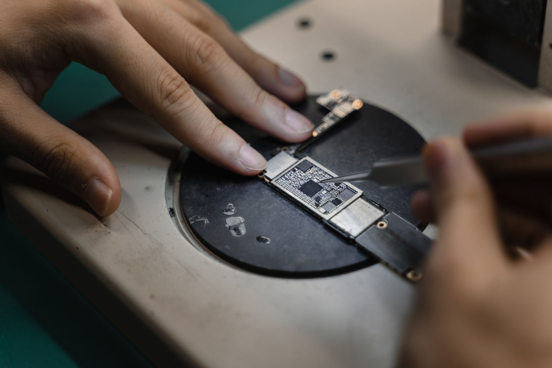
Conductive material moves charge quickly. Static-dissipative material releases it more gradually. Insulative material can retain charge and create an electric field near exposed components. The correct mix depends on the payload, personnel safety requirements, and the approved grounding scheme, so color or a generic antistatic label proves very little.
Treat the load deck and carrier as worksurfaces. Measure through the finished assembly, including paint, anodizing, laminate, adhesive, fasteners, liners, hinges, and removable trays. A conductive polymer panel can still float electrically when insulating washers, powder coating, or adhesive isolate it from the grounded frame.
NASA's published ESD workmanship standard illustrates the distinction with specific facility limits: conductive floor surfaces are below 10^6 ohms, while dissipative floor surfaces span 10^6 to less than 10^9 ohms. Those are NASA requirements, not automatic limits for every factory, but they show why conductive and dissipative should never be treated as marketing synonyms.
How should you evaluate wheels and floor contact?
The wheel system is often the mobile ground path, and it is also a wear item exposed to dust, flux residue, oils, tire dressing, floor finish, and embedded debris. Specify conductive or dissipative tread, a bonded path through the hub and bearings, and compatibility with the exact EPA floor. Then test the complete wheel-to-floor-to-ground circuit.
Evaluate drive wheels and casters separately. Steering, acceleration, braking, ramps, thresholds, and uneven floors can unload one wheel or interrupt contact. Redundant paths are preferable because a single qualifying wheel may cease to conduct during a turn. Drag chains require equal scrutiny around expansion joints, floor gaps, contamination, and dock plates.
Resistance at rest is only the first screen. Log body or chassis voltage while the loaded robot runs its actual route, turns tightly, crosses seams, brakes, and docks. Repeat with new wheels, representative worn wheels, and the permitted contamination level. Wheel cleaning and replacement intervals belong in the robot maintenance service plan.

Ground the carrier, not just the robot

A removable cart, tote rack, roller top, lift table, or tugged train can break the conductive chain. Bond metal sections together and provide a deliberate connection between carrier and robot. Spring contacts, conductive locating pins, bonded couplers, and monitored ground contacts are useful only when alignment tolerance, corrosion, wear, and cleaning have been tested.
Measure from each payload-contact location to the intended ground path in every mechanical state: carrier absent, latched, lifted, lowered, loaded, and partially engaged. Include shelves at different heights and removable inserts. If the payload remains inside qualified protective packaging throughout travel, record that control explicitly rather than assuming the carrier provides protection.
For perspective, NASA's standard requires mobile equipment tied directly to a common point ground to measure less than 1 ohm. Equipment grounded through conductive or dissipative flooring must measure from 10^6 to less than 10^9 ohms. A plant should use its own approved limits, but the measurement boundary must include the complete carrier assembly.
Docking is the critical transfer event
Docking changes the robot's electrical state. Charging contacts may engage, wheels may unload, a lift may raise the carrier, and a tote may cross onto fixed equipment. At the same moment, packaging can open and expose sensitive assemblies. Validate the sequence, not merely the two endpoints.
Design the handoff so the grounded or equipotential connection is established before an exposed device can approach a new surface. Maintain that path until the device is enclosed, grounded at the destination, or returned to qualified packaging. Check for charge sharing between the robot, carrier, dock, conveyor, operator, and product fixture.
Run fault cases as well as normal cycles. Test a missed latch, dirty contact, partially seated carrier, power loss, emergency stop, aborted transfer, manual recovery, and charging without a payload. The control system should block transfer or issue a clear alarm when monitored grounding conditions are outside the approved range.
- Measure the dock, carrier, and robot before contact, during first contact, after latching, throughout transfer, and during separation
- Record resistance, chassis voltage, carrier voltage, and nearby electric fields with calibrated instruments suited to the plant standard
- Test loaded and empty cycles at normal and worst-case speed, acceleration, humidity, and floor condition
- Confirm that operators remain grounded during manual loading, unloading, jam clearance, and recovery
- Verify that charging hardware, communication cables, and protective-earth connections do not create an unintended path or isolated conductor
How do you validate the AMR in the plant?
Start with a bench review of drawings, material data, qualification reports, and replacement-part controls. Next, conduct a controlled robot pilot program on the production floor. Instrument the complete route and challenge the states most likely to generate or trap charge, including long runs, tight turns, rapid stops, carrier exchange, and docking.
The ESD Association says footwear-flooring personnel grounding systems should remain below 1.0 x 10^9 ohms and produce less than 100 volts in the prescribed walking-voltage test. That test applies to people, not robots, but it demonstrates an important principle: resistance and generated voltage answer different questions. An AMR should likewise be checked for both continuity and charge generation.
Qualify at the environmental condition required by the plant's program. The ESD Association reports that traditional low-humidity conditioning is commonly 12 percent plus or minus 3 percent relative humidity at 23 degrees Celsius plus or minus 3 degrees, while current standards can permit qualification at the facility's lowest annual humidity. Do not validate only on a humid afternoon and assume winter performance.
- Map measurement points and acceptance limits before testing begins
- Use calibrated resistance meters, electrodes, field meters, and contact voltmeters appropriate to the approved methods
- Test every carrier type, payload orientation, route surface, dock, and manual recovery procedure
- Capture serial numbers, wheel age, floor condition, temperature, humidity, software version, payload, and instrument calibration
- Retest after maintenance, wheel replacement, carrier repair, route changes, floor refinishing, or dock adjustment
Turn acceptance data into a maintainable deployment
ESD performance erodes through ordinary operations. Wheels glaze, contacts oxidize, coatings scratch, floors acquire residue, and replacement components arrive with different electrical properties. Define inspection points, test intervals, cleaning materials, limits, escalation rules, and quarantined states before go-live support ends.
Service Robot Co. approaches electronics AMR selection as an OEM-neutral integration problem. As a vendor neutral robot integrator, we compare machines across manufacturers, then handle robot deployment and integration, financing, training, and service through a nationwide US engineer network. That gives a manufacturer one accountable vendor for the robot, carrier, dock, and lifecycle records.
This model also supports autonomous mobile robot leasing, material handling robot leasing, and phased deployment no shutdown when those commercial structures fit the plant. The engineering gate remains the same under a purchase, lease, or amr leasing: no unit enters production until the installed workflow passes the customer's documented ESD acceptance criteria.
Frequently asked questions
Sources
- ANSI/ESD S20.20-2021 official standard page
- IEC 61340-5-1:2024 official publication
- ANSI/ESD STM4.1-2026 official standard page
- ESD Association control procedures and material limits
- ESD Association automated handling equipment guidance
- NASA-STD-8739.6B ESD workmanship standard
- ESD Association guidance on humidity controls
- ESD Association facility certification requirements