
Key takeaways
- Test every route at the heaviest approved payload and most unfavorable center of gravity.
- Measure rollback, stopping distance, wheel slip, lateral drift, and payload movement rather than judging appearance.
- Repeat trials on dry, damp, and operationally realistic wet transitions under controlled conditions.
- A pass requires repeatable performance without manual help, uncontrolled motion, contact, or load instability.
- Record surface conditions and configuration so the test can be repeated after maintenance or site changes.
What does a passing mobility test prove?
A robot passes mobility validation only when it can climb, descend, stop, restart, and cross every relevant floor transition with its approved payload, without uncontrolled rollback, persistent wheel spin, route departure, contact, or load movement. The test must reproduce the geometry and surface conditions the robot will encounter during normal work.
A dry commercial robot demo is not enough. Water, detergent residue, condensation, dust, worn coatings, and a wheel crossing an expansion joint can reduce available grip or disturb the chassis. A robot that looks composed while empty on clean concrete may behave quite differently when loaded near its rated limit.
Treat the exercise as a measured robot pilot program, not a showroom performance. Define the route, loads, conditions, repetitions, failure rules, and recovery procedure before the first run. The result should be evidence that operations, safety, and facilities teams can approve together.
Which route features belong in the test map?
Start with a physical survey. Measure each ramp's rise, run, length, cross slope, grade breaks, landing space, and approach angle. Record thresholds, dock plates, drainage channels, mats, grout lines, cracked patches, elevator gaps, and expansion joints along the intended route.
The U.S. Access Board provides useful building baselines, though they are not robot performance ratings. An accessible ramp generally has a maximum running slope of 1:12, or 8.33 percent, and a maximum cross slope of 1:48. A walking surface steeper than 1:20 is treated as a ramp under the accessibility guidance.
Threshold geometry matters just as much as the long slope. The Access Board permits an untreated vertical change up to 1/4 inch. A change between 1/4 and 1/2 inch must be beveled no steeper than 1:2, while a larger change must be handled as a ramp. Measure the actual facility rather than assuming construction drawings match the worn floor.
Mark each feature on the site assessment mapping file with direction of travel. A joint crossed squarely can feel benign, while the same joint approached diagonally may unload one drive wheel and introduce yaw. Include both directions whenever the operating route uses both.
- Ramp pitch and cross slope at the steepest measured points
- Length and level runout available for braking
- Threshold height, bevel, width, and approach angle
- Expansion-joint width, depth, filler condition, and edge damage
- Surface material, coating age, visible wear, and drainage pattern
- Nearby walls, curbs, doors, pedestrians, and fall edges
How should payload and surface conditions be prepared?
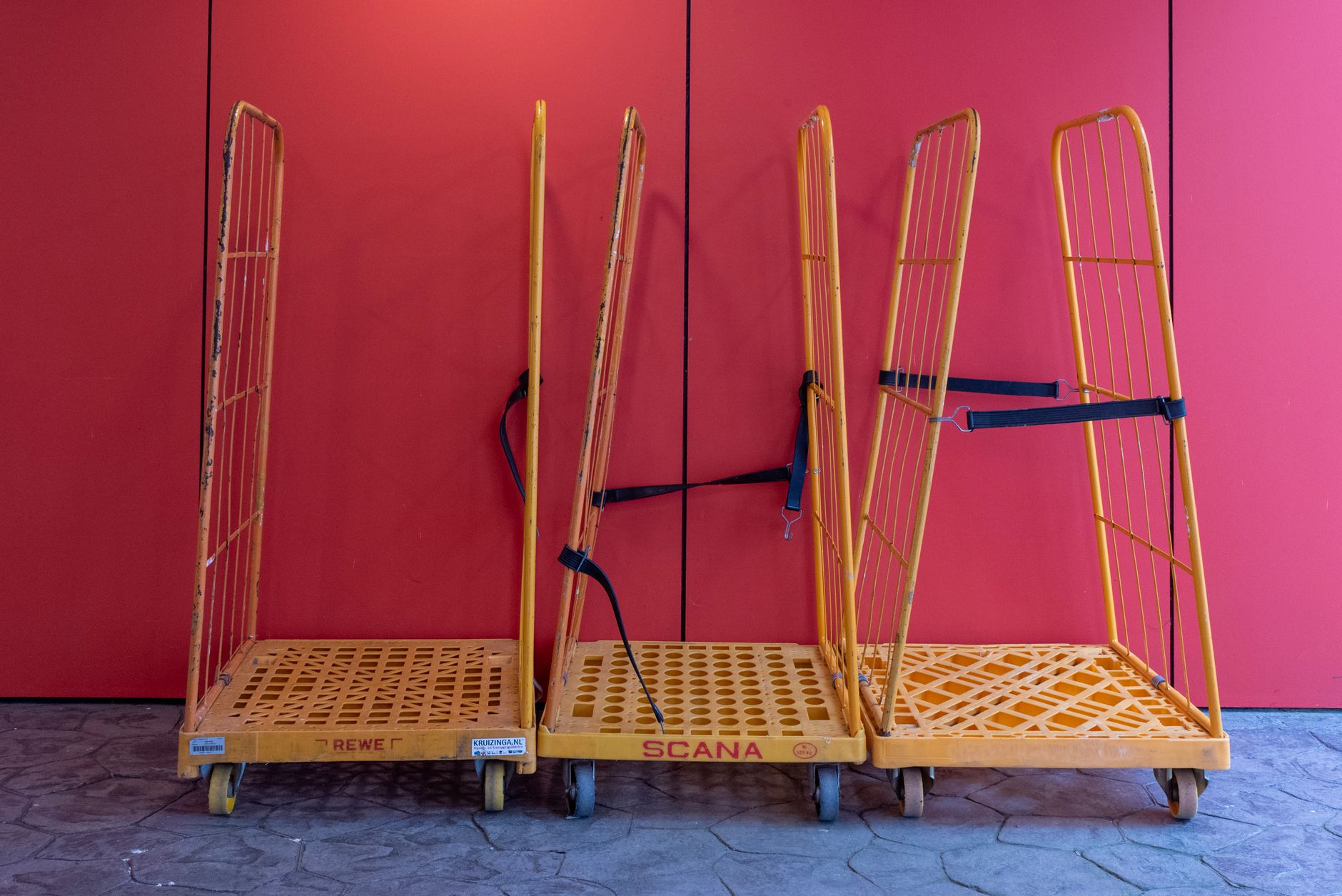
Run three payload states: empty, the normal working load, and the maximum load approved for that application. For a cart-pulling or material handling robot leasing, include the real cart, caster condition, coupling, and load distribution. For a delivery robot, reproduce the least favorable shelf position and center of gravity.
Use secured inert ballast when live goods would create unnecessary risk. Weigh the complete payload and photograph its position. A tall load, liquid container, hanging item, or free-rolling cart can become unstable before the robot itself approaches a rollover limit.
Test the floor dry first, then introduce controlled conditions that genuinely occur at the site. Those might include clean water at an entrance, correctly diluted cleaning chemistry, tracked-in moisture, or condensation at a temperature boundary. Isolate the test area, use a measured application method, and restore the floor afterward.
OSHA requires workplace floors to be maintained clean and, to the extent feasible, dry. It also identifies leaks, spills, snow, and ice as hazards requiring correction. Mobility testing does not authorize routine travel through an uncontrolled spill. It establishes how the robot behaves at predictable wet transitions and confirms that detection, exclusion, and cleanup rules work.
What maneuvers expose traction and braking limits?
Begin below the operating limit and increase difficulty only after clean runs. Drive straight uphill at normal route speed, stop at the steepest point, hold, restart, and finish the climb. Repeat downhill, including a commanded stop where the robot has enough runout to remain inside the isolated test zone.
Next, test low-speed entry and exit at each grade break. A chassis may retain grip on the ramp yet scrape, pitch sharply, or momentarily unload a wheel where the slope meets a landing. Cross thresholds and joints at the actual route angle, then at the least favorable credible angle.
Add cross-slope travel only where the production route requires it. Observe downhill drift, steering correction, caster behavior, and payload lean. Do not improvise aggressive turns on a ramp merely to find a dramatic failure. The test boundary should come from the risk assessment and intended operation.
NIST's repeatable mobility work offers a useful principle: one successful pass says little. Its published methods use repeated courses, including 10 figure-eight repetitions in a crossing-ramp test, and its test arenas include continuous 15 degree pitch and roll flooring. Those figures are not automatic acceptance limits for a commercial facility, but they illustrate why repeatability and controlled geometry matter.
- Steady climb and descent at the configured operating speed
- Stop, hold, and restart at the steepest route point
- Emergency or protective stop under the approved test procedure
- Threshold and joint crossing in every production travel direction
- Ramp entry and exit with the longest and least favorable payload
- Wet-transition crossing after tire wetting, not only on the first approach
How do you measure wheel slip and payload stability?
Use more than visual judgment. Place measurement marks beside the route and record synchronized video from the side and downhill end. Capture commanded speed, measured speed, wheel speed, motor current, inertial data, safety events, and localization quality when the platform exposes those signals.
A wheel-speed increase without matching chassis movement indicates slip. Other clues include tire polish marks, oscillating steering corrections, motor-current spikes, sideways displacement, or a climb that takes longer with each repetition. Record the location and surface condition for every event.
For stopping, measure from the stop command or defined protective-field trigger to complete rest. Also record rollback after stopping on the incline and movement during the hold period. The acceptance boundary must come from the application's risk assessment, available clearance, speed, payload, and the robot's configured protective functions.
Track payload displacement with witness marks, a fixed camera, or a simple displacement gauge. Reject contact between the load and enclosure, opening doors, shifted containers, excessive liquid movement, coupling lift, caster shimmy, or any change that could alter braking and steering on the next maneuver.
- Completion time and speed variation
- Stopping distance and final resting position
- Rollback or downhill creep during hold
- Wheel-slip duration and distance lost
- Lateral drift from the route centerline
- Pitch, roll, and payload displacement
- Faults, protective stops, manual assists, and recovery time

What acceptance criteria should the team use?
Write the pass criteria before testing. A practical site acceptance gate is 10 successful repetitions in each required direction for every approved combination of route, payload, and surface condition. Ten is a defensible repeatability target inspired by NIST's published mobility method, not a universal legal threshold. Increase the sample when conditions vary widely or a failure could have serious consequences.
Every run should finish without manual assistance, unintended contact, route-boundary departure, uncontrolled rollback, sustained wheel spin, payload shift, or an unexplained fault. Stopping distance must remain inside the documented safety envelope on the least favorable tested surface. The hold brake must prevent downhill creep for the defined dwell period.
Set quantitative limits for lateral drift, allowable payload movement, completion time, temperature, and battery state using the application risk assessment and supplier documentation. Do not average away a dangerous outlier. A single loss of control, spill, collision, or departure toward an edge is a failed condition that requires investigation and retesting.
ISO 3691-4:2023 covers safety requirements and verification for driverless industrial trucks, including autonomous mobile robots. Its scope includes movement stopping, truck holding, load handling, steering, and stability. The current ANSI/A3 R15.08 series likewise addresses industrial mobile robot design, integration, use, risk assessment, and management of environmental change. Use the standards applicable to the machine and site with qualified safety personnel.
- All scheduled repetitions completed without intervention
- No uncontrolled rollback, downhill creep, or persistent wheel spin
- Measured stop remains within the approved clearance envelope
- No collision, scrape, bottoming, or safety-field violation
- No payload displacement beyond the documented limit
- No thermal, traction, localization, or braking fault left unexplained
Why is a dry demonstration insufficient?

Traction is an interaction among tire material, tread condition, normal force, surface texture, contaminant, speed, and control tuning. Change one element and the available grip can change. Moisture can also migrate from a wet zone onto an apparently dry ramp as the wheels make repeated passes.
Dry tests often hide cumulative effects. Tires collect dust, caster bearings warm, batteries discharge, and cleaning chemistry spreads beyond the original patch. A robot may complete the first crossing neatly and begin slipping on a later stop or restart.
NIST reports slippage, uneven flooring, vibration, heavy loads, and dynamic loads among issues encountered in mobile-robot testing. Its updated mobility research also reports completed methods for weighted driving, driving and docking on ramps, and load stability. That combination supports testing the real system under repeatable environmental conditions, not relying on an empty dry-floor run.
Wet testing must still be controlled. Establish barriers and spotters, start with low speed, keep personnel out of the downhill path, and provide a remote stop method. Stop the trial if contamination spreads beyond the marked area or the robot approaches the predetermined boundary.
From pilot result to production control
Preserve the test package: route drawings, measurements, surface preparation, payload photos, software and firmware versions, tire condition, battery state, raw telemetry, videos, deviations, and approvals. This becomes the baseline for change control and future maintenance checks.
Retest after tire changes, control updates, payload redesign, floor recoating, threshold repair, ramp modification, route remapping, or a traction-related incident. Seasonal entrance conditions may justify a separate validation before rain, snow, or deicing residue becomes common.
Service Robot Co. handles this work as part of robot deployment and integration. As an OEM-neutral, vendor neutral robot integrator, we compare machines against the customer's actual geometry and duty rather than forcing one catalog choice onto every floor. The aim is a robot that fits your floor, payload, traffic, and operating rules.
Customers can use a commercial robot demo or structured try before you buy pilot, then choose purchase or lease arrangements that fit the deployment. Service Robot Co. can finance, deploy, integrate, train, and service each unit through a nationwide U.S. engineer network, giving operators one partner and one number across the fleet lifecycle. Available programs can include RoboCare™ service, remote triage, on-site dispatch, and go-live support.