
Key takeaways
- Repeatable camera position and load context make thermal images comparable over time.
- Bare bus metal can reflect heat, so emissivity and reflected temperature must be controlled.
- Stand-off distance is governed first by electrical hazards, then by camera resolution.
- Thermal alerts indicate abnormal heat, but a qualified electrician determines the cause and response.
- A mobile route supplements an electrical maintenance program. It does not replace required inspections or testing.
What does a mobile thermal route reveal?
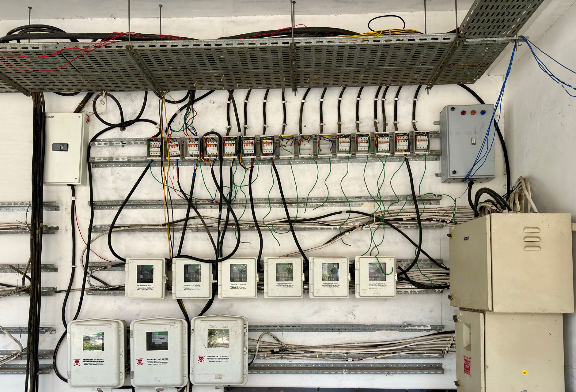
A mobile inspection robot can repeatedly scan bus ducts, busway joints, tap boxes, switchgear, panelboards, transformers, and other distribution equipment for developing hot spots. Its chief advantage is repeatability. The robot can return to the same waypoint, face the same target, and capture a radiometric image from nearly the same angle every time.
That consistency makes subtle change visible. A warm splice that once resembled adjacent joints may begin separating from its baseline over several routes. The system can flag the change for review before discoloration, odor, nuisance tripping, or an outage makes the problem obvious.
The robot is a data collector, not an electrician. Its findings should enter the facility's electrical maintenance process, where a qualified person reviews the thermal pattern, operating load, equipment history, and risk before deciding what happens next.
Why are busways well suited to repeatable inspection?
Bus duct systems distribute high current across long, segmented runs. Each joint, elbow, tap-off point, termination, and transition introduces a location worth comparing. Connections can heat because of resistance, loading, phase imbalance, installation defects, contamination, corrosion, or mechanical deterioration.
A handheld survey may cover these assets effectively, but recreating dozens or hundreds of camera poses is difficult. A mapped robot route can assign a stable asset ID and viewing pose to every accessible target. The resulting record ties each image to a physical point instead of leaving staff to interpret filenames and room descriptions.
Routes should include the complete electrical path, not only the straight busway. Useful targets include feeder terminations, splice covers with approved viewing provisions, tap boxes, disconnects, breaker line and load sides, neutral connections, and transitions into distribution gear. Obstructions, closed metal covers, and insulation can conceal internal heat, so route designers must document what the camera cannot see.
How should emissivity be handled?
Infrared cameras infer surface temperature from detected radiation. Emissivity describes how effectively a surface emits that radiation. Polished aluminum and copper have low emissivity and can behave like infrared mirrors, producing apparent hot or cold areas caused by nearby equipment, people, lights, or the camera itself.
Fluke's published reference table lists polished aluminum at 0.05, polished copper at 0.01, black-oxidized copper at 0.88, and black plastic electrical tape at 0.95. Those differences are large enough to make an uncorrected temperature reading on bright bus metal misleading. Camera software cannot rescue a measurement when the surface condition and reflected background are unknown.
Approved high-emissivity targets can improve repeatability. Fluke describes electrical tape set to 0.95 emissivity, with an appropriate reflected-background correction, as a way to measure reflective surfaces with stated accuracy of plus or minus 2 degrees Celsius or 2 percent of the reading. Any tape, coating, label, or target inside electrical equipment must be selected and installed during a safe, authorized condition by qualified personnel. A robot must never apply it to energized buswork.
Each inspection point should retain its emissivity setting, reflected apparent temperature, target material, viewing angle, distance, focus, and camera range. Changing one of those inputs between routes can create a false trend.
Why does load context matter?
Electrical heat is inseparable from current. A poor connection may look ordinary during light production and become conspicuous near peak demand. Conversely, two scans made at very different loads can show different temperatures even though the connection has not changed.
A public NFPA 70B committee record calls for thermography at normal online loading, documentation of temperature difference, and retention of circuit-loading characteristics. Its annex language identifies 40 percent of nominal circuit loading when normal loading is not feasible. The practical goal is not to chase one number. It is to compare like operating states and record exceptions honestly.
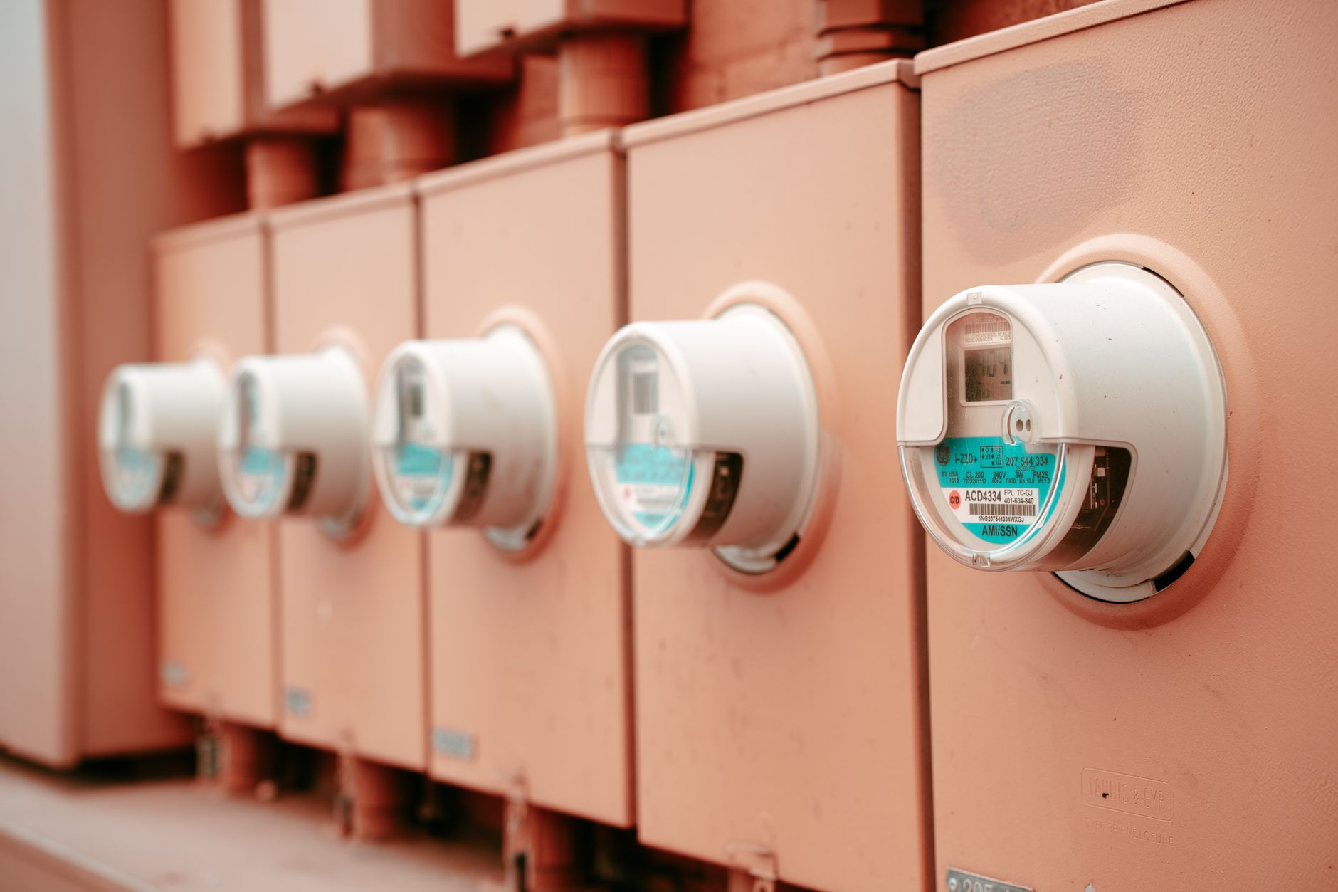
At each route, capture available phase current, percent loading, ambient temperature, production state, cooling or ventilation status, and time since a major load change. Current should come from approved meters or facility systems, not from a mobile robot probing energized conductors. Allow equipment to approach thermal equilibrium before treating a reading as a dependable baseline.
A route taken at 28 percent load can still provide useful evidence, but it should not be silently compared with a 78 percent-load scan. Trend software should filter or normalize comparisons by load band and send uncertain cases to a thermographer or electrician.
What makes a route genuinely repeatable?
Repeatability requires more than sending an autonomous mobile robot through the same corridor. Every target needs a defined stopping zone, camera height, pan and tilt, focus distance, framing rule, and asset label. The visible image should be stored beside the thermal image so reviewers can confirm that the robot observed the intended joint or enclosure.
Camera resolution determines how many detector pixels cover the target at a given distance. A joint occupying only a few pixels may be detectable as warm but unsuitable for a defensible temperature measurement. Commissioning should prove the smallest important target at the farthest permitted position, then lock that geometry into the route.
Useful quality gates include focus score, target occupancy, viewing-angle tolerance, obstruction detection, camera calibration status, ambient conditions, and load-data freshness. A failed quality gate should produce a rescan request or an inconclusive result, not a confident alarm.
Route frequency should follow the electrical maintenance program and asset condition. NFPA's published development record for the 2026 edition of NFPA 70B lists infrared thermography intervals of 12 months for condition categories 1 and 2 and 6 months for condition 3. A facility may choose additional robot rounds for critical or deteriorating assets, but those rounds should complement the governing maintenance plan.
How is a safe stand-off distance established?
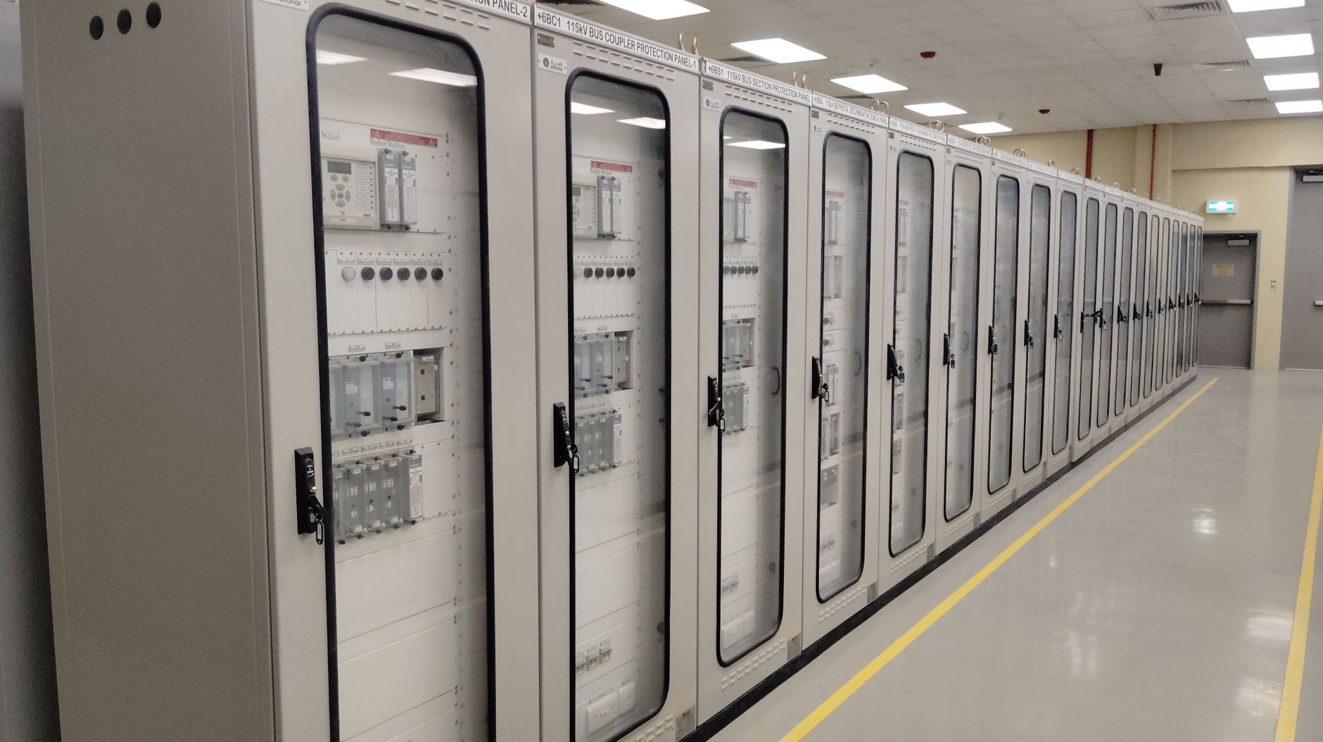
There is no universal robot distance for energized bus duct inspection. The approved position must account for nominal voltage, enclosure condition, exposed parts, shock boundaries, arc-flash boundary, incident energy, grounding, room geometry, camera capability, and the site's electrical safe-work practices. The controlling electrical boundary takes precedence over image quality.
Keep routine routes outside guarded electrical working spaces unless an electrical risk assessment explicitly authorizes the equipment and route. Closed, correctly secured enclosures and permanent infrared viewing windows can reduce exposure, but a viewport has its own transmission characteristics and must be compatible with the camera's spectral range.
OSHA requires appropriate protective equipment where electrical hazards exist and calls for barriers or insulating materials where dangerous heating or arcing could occur. OSHA also states that only qualified persons may perform testing work on electrical circuits or equipment. A remote robot can reduce the time people spend near energized assets, but it does not cancel those requirements.
Map a hard geofence around each prohibited area and test stopping performance on the actual floor. Account for localization error, obstacle avoidance, payload overhang, antenna height, conductive attachments, door movement, and loss-of-communications behavior. If safe clearance and adequate thermal resolution cannot coexist, change the optical arrangement or install an approved viewing provision during a planned outage.
How should thermal trends become maintenance decisions?
Trend the same region of interest rather than merely comparing each image's hottest pixel. Record absolute apparent temperature, temperature rise over ambient, difference from comparable phases or parallel components, load, and rate of change. A persistent upward drift under similar conditions is often more persuasive than a single dramatic frame.
Automated rules can screen for phase asymmetry, localized gradients, departures from baseline, and accelerating temperature rise. They should also suppress common artifacts such as reflections that move when the camera angle changes, passing workers, sunlight, hot air discharge, and incorrectly matched assets.
Alarm levels belong in an electrician-approved decision matrix. A newly observed severe anomaly may prompt immediate operating review, while a mild but repeatable rise may justify a shorter rescan interval. The record should preserve the original radiometric file, visible image, analysis settings, route quality data, and every acknowledgment or disposition.
After repair, repeat the route under comparable load to verify the thermal pattern changed as expected. Closing an alert only because a work order was completed severs the evidence chain. Post-work verification turns the robot route into a maintenance feedback loop.
Where does Service Robot Co. fit?
A dependable program joins mobile autonomy, thermal optics, electrical work practices, facility data, and field service. Service Robot Co. acts as an OEM-neutral commercial robot integrator for U.S. businesses, selecting equipment across manufacturers and handling financing, deployment, integration, training, and service through a nationwide engineer network.
That one-vendor lifecycle is useful when an inspection robot lease must connect with asset registers, work-order systems, current data, and remote review. Available program structures can include autonomous mobile robot leasing, robot leasing for business, monthly payment programs, a commercial robot pilot program, or purchase. The commercial arrangement should follow the validated technical case.
During site assessment mapping, Service Robot Co. can help define routes, target poses, communications coverage, charging locations, geofences, recovery procedures, and robot fleet management. The facility's electrical authority remains responsible for electrical safety rules, access permissions, interpretation, and corrective work. That division keeps robot deployment and integration tied to the right professional judgment.
A practical commissioning sequence
Start with an electrical asset register and single-line context. Rank busway sections and distribution equipment by criticality, consequence of failure, condition, and accessibility. A qualified electrician or thermographer should then identify legitimate thermal targets and known blind spots.
Next, capture a human-reviewed baseline under documented load. Validate emissivity treatment, reflected temperature, focus, target pixel coverage, and every safe camera pose. Run the robot repeatedly to measure positional variation and confirm that an operator can recover it without entering a restricted area.
Finally, test the full alert chain. Seed known image-quality failures, missing load records, communications loss, and a simulated abnormal trend. A pilot is ready to scale only when the system can distinguish an actionable anomaly from an inconclusive scan and route both outcomes to the correct reviewer.
- Assign a unique ID to each joint, tap box, termination, and comparison component.
- Document approved stand-off positions and hard electrical geofences.
- Store radiometric and visible images with load and environmental context.
- Require electrician disposition, priority, and follow-up date for every confirmed alert.
- Verify corrective work with a comparable post-repair scan.